The clock module generates the timing signals that drive the entire computer.
Components Needed:
- 555 Timer IC
- Resistors: 1kΩ, 10kΩ
- Potentiometer: 10kΩ (optional for adjustable frequency)
- Breadboard
- Jumper wires
Steps:
- Place the 555 Timer on the Breadboard:
- Orient the IC so that the notch or dot marking pin 1 is on the top left.
- Insert the 555 Timer into the breadboard, spanning the middle gap.
- Connect Pin 1 (GND) to Ground:
- Use a jumper wire to connect pin 1 to the ground rail on the breadboard.
- Connect Pin 8 (VCC) to Power:
- Use a jumper wire to connect pin 8 to the +5V power rail.
- Connect Pin 4 (Reset) to VCC:
- Use a jumper wire to connect pin 4 directly to pin 8.
- Connect Pin 2 (Trigger) to Pin 6 (Threshold):
- Use a short jumper wire to connect pin 2 and pin 6.
- Connect Pin 6 to a Capacitor:
- Place one lead of the 10µF capacitor to pin 6 and the other lead to ground.
- Connect Pin 7 (Discharge) to a Resistor and Capacitor:
- Connect the 1kΩ resistor between pin 7 and the positive rail.
- Connect the 10kΩ resistor between pin 7 and pin 6.
- Optionally, add the 10kΩ potentiometer between pin 7 and pin 6 to adjust the frequency.
- Connect Pin 5 (Control Voltage):
- Place a 100nF capacitor between pin 5 and ground.
- Connect Pin 3 (Output) to an LED:
- Connect a current-limiting resistor (e.g., 220Ω) to pin 3.
- Connect the other end of the resistor to the anode (long leg) of an LED.
- Connect the cathode (short leg) of the LED to ground.
- Power the Breadboard:
- Connect the 5V power supply to the power rails.
- Ensure the power supply is correctly polarized.
- Test the Clock:
- When powered, the LED should blink at the rate set by the 555 Timer.
- Adjust the potentiometer to change the blink rate if included.
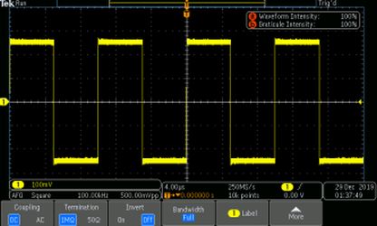
- Important: Make sure that your connections are all correct using the Oscilloscope, a device used for viewing oscillations as of electrical voltage or current

An oscilloscope displaying a square wave